All published articles of this journal are available on ScienceDirect.

A Frameless Stereotaxic MRI Technique for Macaque Neuroscience Studies
Abstract
MRI has achieved widespread use for preplanning neuroscience procedures for non-human primate studies. However, orienting imaging studies in stereotaxic space has relied primarily on using a stereotaxic frame or co-registering fiducial markers with the neuroimaging. In this study, we present a simple approach in which the MRI dataset is aligned to the bony landmarks that define the Frankfurt stereotaxic baseline plane, without the need for a stereotaxic frame or additional external fiducials. To facilitate localizing the bony landmarks (infraorbital margin, external bony auditory meatus) on the MRI scans additional imaging landmarks (mid ocular plane, temporomandibular joint) are discussed that provide supplementary and readily visible points of reference.
The frameless MRI stereotaxic technique was evaluated in 8 rhesus macaque monkeys using 3D fast gradient echo MRI images with 0.7mm isotropic resolution. 1) Difference in stereotaxic coordinates of fiducial markers was compared between a traditional stereotaxic frame and the frameless MRI technique (n=2). 2) Differences in stereotaxic coordinates for cerebral regions were compared between the frameless MRI technique and MRI obtained with the animal positioned in a MRI-compatible stereotaxic frame (n=4). 3) The frameless MRI technique was further refined to prescribe electrode penetrations within a dural recording chamber in stereotaxic coordinates relative to the electrode microdrive. Differences in MRI coordinates were compared with the electrode microdrive (n=3).
Mean localization of fiducial markers differed by 1.6 +/- 0.6 mm between the frameless MRI technique and a traditional stereotaxic frame. Between the frameless technique and an MRI-compatible stereotaxic frame, localization of cerebral anatomy differed by 2.8 +/- 2.2 mm with the primary source of error being a pitch-up rotation in the sagittal plane. This localization difference was reduced to 0.5 +/- 0.6 mm when this rotation was removed. Frameless MRI coordinates for electrode tracts within the dural recording chamber were within 0.5mm +/- 0.2 mm of the electrode microdrive readings.
This simple technique provides the ability to accurately plan surgery and neurophysiological recordings in an individual animal, and to define the location of cerebral anatomy and electrode or injection tracts using publically available software, and without the need for dedicated MRI-compatible localization hardware. The reduced need for deep anesthesia (a necessity with traditional stereotaxic frames) makes the technique more amenable for functional MRI studies. Since each animal provides the bony landmarks to define their own stereotaxic space, this technique is readily applicable to other species.
INTRODUCTION
MRI of the non-human primate brain provides exquisite soft tissue contrast for anatomical or pathological studies as well as functional localization of the hemo-metabolic changes that accompany cerebral activivation [1-7]. Combining MRI with traditional electrophysiology allows correlation of neuronal and hemodynamic cerebral changes [2, 8, 9]. For this, accurate co-registration of the recording electrodes and MR images is crucial.
One approach to coregistration is to perform electrophysiology and MRI contemporaneously [8]. This has the advantage of directly visualizing the position of arecording electrode on the MR images as well as ensuring exact timing of events between the two techniques, but puts tremendous technical constraints on both the MR imaging and the electrophysiology. A more straightforward method is to know the absolute stereotaxic coordinate of the recording electrode (or other hardware), and to acquire the imaging separately in the same coordinate space. Aligning the skull, based on the position of specific bony landmarks in a stereotaxic frames, has changed little since its initial description a century ago [10]. For MRI, a minor modification has been to use a frame remanufactured for MR compatibility, to correctly orient the animal within the MRI bore [11-14]. While simplistic in its approach, the necessity for rigid fixation of the head in an external frame requires deep anesthesia, which may significantly diminish the BOLD signal, making functional MRI much more challenging [7,8]. Although the skull and frame are aligned, particular attention is still needed to ensure the stereotaxic frame itself is aligned with the cardinal axes of the MR scanner. Other studies have used fiducial markers on the skin or implanted into the skull to coregister the anatomy with the images [14-18].
In this paper, we investigate the utility of a novel frameless method for imaging the macaque brain in standard stereotaxic coordinates. For this, the position of the animal within the MRI scanner can be arbitrary, as the images rather than the animal are rotated into the correct plane. To assess the accuracy of this technique, the stereotaxic location of MRI-compatible fiducial markers from our frameless MRI technique were evaluated against a traditional (neurosurgical) stereotaxic frame. In a second study, the location of cortical and deep brain structures determined by the frameless MRI technique were compared with those measured using a MRI-compatible stereotaxic frame within the MRI bore.
For interventions within a dural recording chamber, the actual coordinate system is arbritary. Thus, the frameless MRI technique was further modified to use the dural recording chamber itself to define the stereotaxic orientation. Using a custom-designed cap for the chamber filled with gadolinium contrast agent, the images could be rotated to align exactly with the brain as "viewed" from the same perspective of the advancing recording electrode. In a third study, the agreement of measurements of cortical position using the electrode microdrive and frameless MRI stereotaxic technique were compared.
MATERIALS AND METHODS
Animals and Stereotaxic Measurements
Cerebral measurements were made in 8 young adult rhesus macaque monkeys. Three comparison studies were undertaken: 1). Fiducial markers were placed on 2 monkeys to compare the frameless MRI technique with conventional stereotaxic measurements. 2). Four further adult rhesus macaque monkeys were imaged in the MRI while positioned in a MRI-compatible stereotaxic frame, and the location of cerebral landmarks compared with those obtained from the frameless MRI stereotaxic technique. 3). MRI measurements from the dural recording chamber were made in 2 additional macaques that had recently undergone extracellular electrode recordings, to compare the frameless MRI technique with the electrode microdrive location. All imaging studies received Institutional Animal Care and Use Committee approval.
MR Imaging:
MRI of the 4 monkeys in the MRI-compatible stereotax frame were acquired at 3 Tesla. The remaining 4 MRI studies without a frame were acquired at 1.5 Tesla (2 comparing MRI localization with conventional stereotax frame localization, and 2 with the electrode microdrive position). All imaging used a T1-weighted 3D Inversion Prepared gradient echo sequence. The locations of the 4 points that define the Frankfurt baseline plane were identified on the MRI and the reconstructed images were transformed to align with this baseline plane using AFNI software (Analysis of Functional Neuroimages, NIMH, USA). In all cases MRI resolution was 0.7mm isotropic, with comparable gray-matter/white matter contrast, and imaging times (8 minutes).
Stereotaxic Baseline and Alignment of MR Images
Theory
The Frankfurt baseline plane as seen on a sagittal MR image and on a corresponding macaque skull is shown in Fig. (1). This plane, also referred to as the Anthropological Baseline, joins the bony inferior orbital rims and the bony external auditory canals. The coordinate system for stereotaxic positioning is based on having the animal’s head oriented so that the Frankfurt plane is horizontal. Once these bony landmarks are identified on MRI, it is possible to transform the MR image into this orientation with simple 3-dimensional rotation irrespective of the animal’s actual orientation in the MR scanner. The standard position for stereotaxic zero is then defined midway between the bony external auditory meati which is where the Frankfurt plane intersects the mid-sagittal plane.
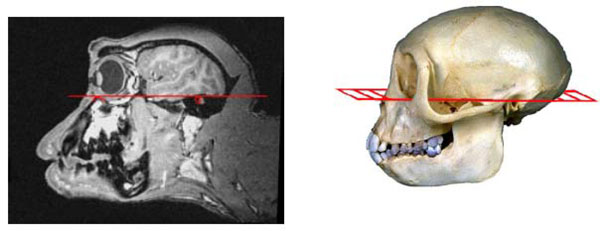
The left image is the Frankfurt baseline plane joining the inferior orbital margin and bony external auditory meatus as seen on MRI. The plane is illustrated on a macaque monkey skull on the right. The MR image is rotated so that the plane joining both inferior orbital mar-gins and both external auditory meatii form a horizontal plane.
Frameless MRI Technique vs. Conventional Macaque Stereotaxic Head Frame
The accuracy of the frameless MRI stereotaxic technique relative to a conventional stereotax frame was evaluated from the position of seven MRI-visible fiducial markers. Four fiducial skin markers were temporarily sutured to the scalp of one animal, and 3 custom made 3mm glass beads filled with 5 microMol gadolinium dimeglimine (Magnavist, Berlex Laboratories, Wayne, NJ) were implanted in a polymethylmethacrylate headcap in a second animal. For conventional stereotaxic measurements, monkeys were anesthetized with isoflurane anesthesia via an endotracheal tube, and positioned in a Kopf macaque stereotaxic frame (Kopf Instruments, Tujunga, CA). MRI for the frameless stereotaxic measurements were acquired during a separate session, also under isoflurane anesthesia.
In a conventional stereotaxic frame, the position of the tip of the meatal bar at the bony external auditory meatus defines stereotaxic zero in the anterior-posterior and superior-inferior directions. To define the position of the bar-ends more accurately relative to actual bony landmarks of the exterior auditory meatus, skull radiographs were taken of the bars in situ. Fig. (2) shows the bar locations on the skull radiographs, and corresponding position superimposed on the macaque skull base, and axial MRI.
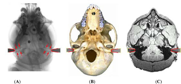
Left image (A) shows the position of the tip of the meatal bars on a skull radiograph. The medial ends of the bars lie just at the opening of the bony external auditory meati. The relationship of the meatal bars to other bony structures of the skull base is superimposed on the skull (B) and relative to other soft tissue structures on MRI (C). Since the auditory canal has an oblique course (arrowed) it is helpful to identify the lateral extent of the bony canal with regard to other anatomical landmarks. Fig. (B) shows the location of the ends of the bars, and hence the auditory meatus, at the junction of the medial ¾ & lateral ¼ of the temporo-mandibular joint (shaded area). Fig. (2B) adapted from http://www.skullsite.co.uk (with permission).
Frameless MRI Technique vs. MRI-Compatible Stereotaxic Head Frame
Four additional animals were positioned in a MRI-compatible stereotaxic head frame (Crist Instrument CO, Inc, Hagerstown, MD)]. The frame with monkey was then positioned in a 3T MRI scanner, with the landmark origin for the scanner at the meatal bars. In the MRI-compatible stereotaxic frame, the animal is already oriented with the Frankfurt plane parallel to the horizontal axis of the scanner, so it is only necessary to set the (0,0,0) origin. The earbars contain a vitamin E contrast media which is easily identifiable on the MR image. The location of the vitamin E defined zero in the superior-inferior and anterior-posterior directions. The midpoint of the bars projected into the midline defined the stereotaxic origin in right-left direction. No additional rotation of the images was required. Images were displayed with AFNI software, with the cursor position corresponding directly to the stereotaxic coordinates. The same images were also used for the frameless stereotaxic MRI technique. To remove any bias, the MR images were initially randomly rotated/shifted, and then subsequently realigned to the Frankfurt plane based on bony landmarks as described above. In this case images were rotated as necessary to ensure that the infraorbital margins and external auditory meati were coplanar. Stereotaxic zero was defined based on bony landmarks projected to the mid-sagittal plane. Stereotaxic coordinates for cortical locations defined by the stereotaxic frame, or framelessly by the bony landmarks were compared for 5 cerebral areas (striate visual cortex, interparietal sulcus, temporal horn of lateral ventricle, arcuate sulcus, superior cerebral peduncle).
Frameless MRI Technique Verses Microdrive Localization of Recording Electrodes
In 2 additional animals, the relative location of recording tracts visible on MRI were compared with the x-y position provided by the electrode microdrive during a prior electrode insertion and removal 24 hours earlier (FHC Inc., Bowdoin, ME
To rotate the cardinal axes for the MR dataset into the same orientation as the recording chamber, a novel fiducial indicator was built into the cap of the dural recording chamber. This consisted of a central hole extending through the cap into the chamber (defining the superior-inferior (z) direction relative to the chamber). This was flanked by two additional blind-ending channels, all 3 channels thus defining the mid-sagittal (y-z) plane. This is shown in Fig. (3). The chamber and central hole as well as the blind channels were filled with 0.5 microM gadopentate dimeglumine for MRI conspicuity. A scribe mark on the recording chamber is used to align polar orientation of the electrode positioning head as well as the fiducial cap, ensuring both are aligned in the same orientation.
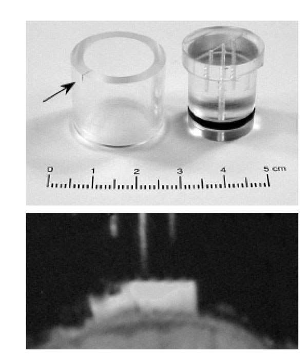
Modified recording chamber cap with central filling hole and two blind channels. The detent on the recording chamber (arrowed) is used to align both the cap (in the MRI) or the electrode microdrive (outside the MRI). The MRI shows a T1 weighted 3D gradient echo image of the chamber positioned over parietal cortex. The image has been rotated to align with the chamber (and the 3 gadolinium-filled holes in the cap) and this is thus a true mid-sagittal image in the orientation of the dural chamber.
The MR image was transformed and displayed using AFNI software so that the (0,0,0) origin was set to align with the center of the chamber (open ended gadolinium-filled channel). The z-origin was defined at the dural surface. By positioning the cursor, stereotaxic coordinates can thus be read straight off the AFNI MRI display. The electrode passed through a sheet of paper, allowing a secondary confirmation of the actual electrode position within the recording chamber.
To assess the accuracy of this technique, comparative measurements of electrode position were made using the electrode positioning head, and by reconstructing the electrode tract visible on the MR images (Fig. 7). Accuracy in the z-direction (depth) was not assessed, as the MR image of electrode tract provides no indication of z-position.
Same data from Fig. (6), but corrected for the 7-degree rotation error of scanner table. This reduced the mean error (Euclidean distance of the offset) to 0.6 mm (S.D. 0.5 mm).
Measurement of Error for Stereotaxic Coordinates
The relative offset for each fiducial or anatomical position were plotted in the 3 cardinal planes - axial (xy), coronal (xz), Sagittal (yx) for each pair of techniques; frameless MRI location vs. conventional stereotaxic frame, frameless MRI location vs. MRI-compatible stereotaxic frame, frameless MRI location vs. electrode microdrive. The discrepancy in location for each point, either anatomical or fiducial, for each technique was expressed as the offset (Euclidean distance) from the zero (no-discrepancy) point. Mean and standard deviation of the offsets were calculated for each pair of techniques evaluated.
RESULTS
Localizing the Bony Landmarks of The Frankfurt Plane
Fig. (2) shows a skull radiograph demonstrating the position of the stereotax bars, which are superimposed on the skull base and axial MRI. The meatal bars barely protrude beyond the opening of the bony canal. The cartilaginous external auditory canal is readily visible on T1-weighted MR images, however the exact opening of the bony (as opposed to cartilaginous) external auditory canal can be a difficult landmark to locate on MRI. Both the cartilaginous and bony canals have an oblique orientation (in a postero-lateral to antero-medial orientation), which varies in obliquity from animal to animal, as well as with age. Thus any ambiguity in determining the right-left position of the bony meatal opening will also result in errors in defining the anterior-posterior location.
To provide additional landmark points, we examined the location of the more easily visible temporomandibular joint relative to the bony external auditory meatus. Both landmarks are readily seen on the skull base (Fig. 2b), with the tip lying at the junction of the medial three quarters / lateral quarter of the temporo-madibular joint (TMJ). This provides a valuable secondary landmark to define the lateral extent of the bony canal more clearly. Fig. (4) shows this location on a coronal MRI indicating the lateral extent of the plane incorporating the bony opening of the external auditory meatus.
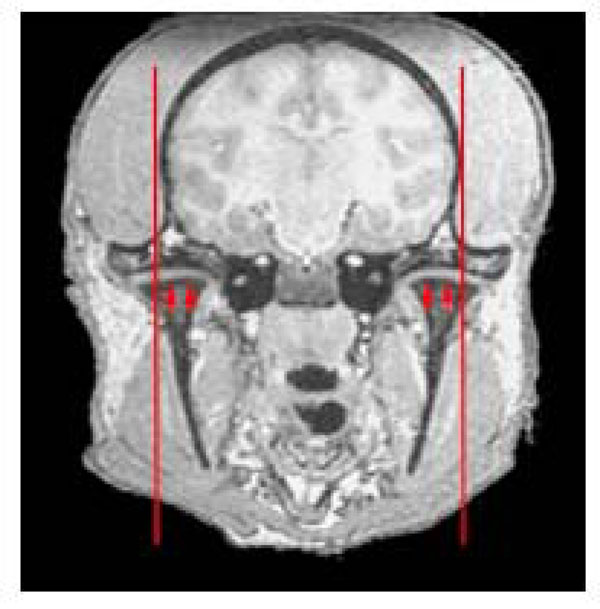
Coronal view through the temporomandibular joints (arrowed). Red line indicated the parasagittal plane corresponding to the opening of the external auditory meatus (meatus not seen on this slice). Note this plane corresponds approximately to the junction of lateral 1/4, medial 3/4 of the temporomandibular joint.
The inferior orbital ridge is also readily visible on the sagittal MRI (see Fig. 1a) and defines the anterior extent of the Frankfurt plane. Since the orbital margin is a curved surface in the coronal plane, it is important to select its most inferior extent. In the anesthetized animal, as the eyes assume a neutral position, this was found to correspond to the mid point of the ocular lens, i.e. the inferior extent of the inferior orbital ridge and the mid point of the lens both lie in the mid-ocular para-sagittal plane. This provided a helpful secondary landmark to locate the trough of the inferior orbital ridge.
Frameless MRI vs. Conventional Stereotaxic Coordinates
The difference in stereotaxic position (in mm) between the stereotaxic frame and MRI images for the 12 fiducial markers (in 2 monkeys) were plotted for the 3 cardinal planes in Fig. (5). The Euclidean distance was calculated for each error measurement. Mean Euclidean offset was 1.6 mm (standard deviation 0.6 mm).
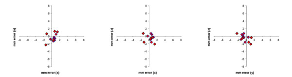
Error in stereotaxic measurement in the 3 cardinal planes (axial, coronal, sagittal) between a conventional stereotaxic frame and the frameless MRI technique for 12 fiducial markers in 2 monkeys. Mean error (expressed as the Euclidean distance of the offset) was 1.6 mm (S.D. 0.6 mm).
Frameless MRI vs. MRI-Compatible Stereotax Frame
The difference in stereotaxic measurement in mm between the MRI-compatible stereotaxic frame and frameless stereotaxic MRI images were plotted for the 3 cardinal planes in Fig. (6). The Euclidean distance was calculated for each error measurement. Mean Euclidean offset was 2.8 mm (standard deviation 2.2 mm).
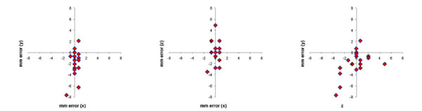
Error in stereotaxic measurement in the 3 cardinal planes between images acquired with a MRI-compatible stereotaxic frame and the frameless MRI technique for 5 cerebral locations in 4 monkeys. Mean error expressed as the Euclidean distance of the offset was 2.8 mm (S.D. 2.2 mm).
We noted a constant 7 degree slant of the MRI-compatible frame relative to the MR Images for all studies representing a small incline of the stereotaxic frame when on the MRI table that had not been previously apparent. When this was accounted for, the mean Euclidian error was reduced to 0.5 mm (sd 0.6 mm) (Fig. 7).
Electrode Position from MRI vs. Electrode Microdrive
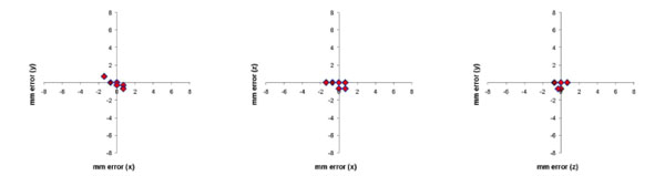
MRI of electrode tracts relative to the dural recording chamber are show in fig. (8). The x-y (axial) difference for the position of the 11 electrode tracts are shown in Fig. (9) for 2 monkeys comparing the positions measured by MRI and by the electrode microdrive (the depth (z) was not measured). The Euclidean distance was calculated for each error measurement. Mean Euclidean offset was 0.5 mm (standard deviation 0.2 mm).
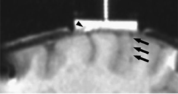
Electrode tract (arrowed) visible on 3D gradient echo images MRI 24 hours after electrode recording in parietal cortex. Areas of dural thickening are also readily outlined by the gadolinium contrast agent in the recording chamber (arrow head).
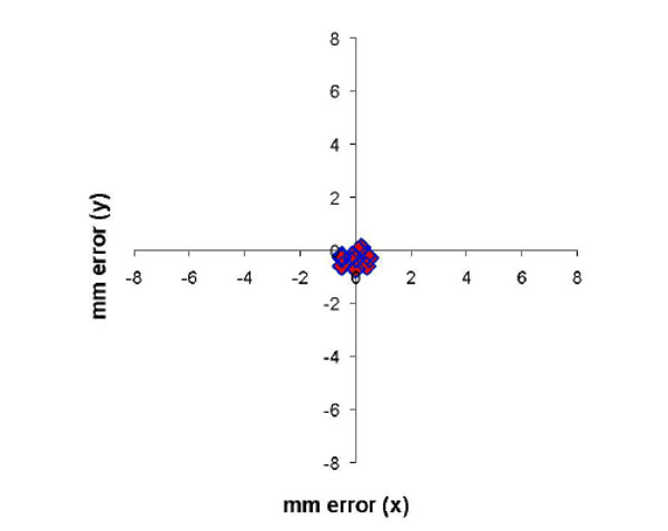
Error in measurement of electrode position relative to the recording chamber in the x-y plane between the position of the electrode microdrive and the frameless MRI technique. Mean error (expressed as the Euclidean distance of the offset) was 0.5 mm (S.D. 0.2 mm).
DISCUSSION
Comparing the frameless MRI technique with conventional external stereotaxic frame coordinates, the mean positional error was 1.3mm. When compared with MRI of the monkey in a MRI-compatible stereotaxic frame the mean positional error was 2.8 mm. MRI-compatable stereotaxic frames provide accurate localization of the animal within the frame, however, these studies have shown that a potential pitfall with the MRI-compatable frame is ensuring it is correctly aligned within the scanner. When the unexpected slope of the frame on the scanner table was corrected, there is very close agreement of the frameless technique with the MRI-compatable frame. The 0.5mm difference in position is at the limit of the image resolution (0.7mm) for the acquired MRI data. This technique thus provides accurate MR localization for surgical placement of imaging and recording hardware, without the necessity for expensive MRI-compatible hardware, and the ability to use much lighter sedation. or even MRI without sedation [1,19]. In addition the ability to image without hardware attached to the animal also considerably reduces image distortion.
Previous authors have advocated that stereotaxic imaging requires that the animal be imaged while in a stereotaxic frame [20]. The close agreement between the frameless technique and a conventional frame means the MRI coordinates reported in this study demonstrated that accurate frameless stereotaxic MRI is readily feasible, and the coordinates can then be transferred directly to an external stereotaxic frame. We have already used this technique for planning neurosurgery, acute electrode placement [7,21] and chronic electrode placements [22].
As with the other studies [23], we found the positional accuracy of this frameless co-registration is sub-millimeter and of the same order as the imaging pixel resolution. For our 3D anatomical MRI sequences, this was 0.7 mm. This small positional error becomes even less of concern when localizing functional MRI studies, where the functional MRI pixel sizes used are considerable larger.
The method described here has been used for planning surgical placement of electrophysiology recording chambers, and for accurately positioning recording electrodes in a specific area of cerebral cortex within a dural chamber [7]. It has also been used to reconstruct the location of electrode recording tracts from the small amount of hemoglobin left in the tract acutely, or the gliosis associated with prolonged electrode recordings [21]. For this study we were not able to assess the positional accuracy for electrode positions in the z-direction (depth), as the exact depth of the electrode penetration was not clearly seen on MRI. The electrode penetration depth is usually referred relative to the external dural surface. Due to variable degrees of dural thickening within a recording chamber, this is not necessarily a constant reference point and thus would only be relevant soon after the MRI has been acquired and before any dural remodeling has had time to take place.
CONCLUSION
The simple frameless MRI stereotaxic technique described here is straightforward to implement using readily available software, and no additional stereotaxic or restraining hardware. It provides comparable localization to conventional stereotaxic frames or imaging localization using MRI–compatible frames. A further modification also allows planning and confirmation of the location of electrode penetrations or microinjection within a dural recording chamber. Since each animal provides the bony landmarks to define their own stereotaxic space, this technique is readily adaptable to other stereotaxic planes [24] or other species.
ACKNOWLEDGMENT
The Authors are grateful to Will Higgs for kind permission to use his skull database (http://www.skullsite.co.uk/) for Figs. (1) and (2). Also to John Reynolds at The Salk Institute for permission to include MRI-compatible stereotaxic frame images from his animals. David Dubowitz is supported by NIH grant NS053934