All published articles of this journal are available on ScienceDirect.
Review of Progress in Atomic Force Microscopy
Abstract
The study of biological samples is one of the most attractive and innovative fields of application of atomic force microscopy AFM. Recent breakthroughs in software and hardware have revolutionized this field and this paper reports on recent trends and describes examples of applications on biological samples. Originally developed for high-resolution imaging purposes, the AFM also has unique capabilities as a nano-indentor to probe the dynamic visco-elastic material properties of living cells in culture. In particular, AFM elastography combines imaging and indentation modalities to map the spatial distribution of cell mechanical properties, which in turn reflect the structure and function of the underlying structure. This paper describes the progress and development of atomic force microscopy as applied to animal and plant cell structures.
1. SURVEY OF METHODS
The work of Elkin et al. [1] on the synopsis of mechanical heterogeneities of the rat hippocampus measured by atomic force microscopic indentation is an example of how measurements have contributed to our understanding of cell mechanics and cell biology and appear to be sensitive to the presence of disease in individual cells. In addition to the many publications which have accrued on these topics, since the development of the atomic force microscope in 1986 much progress has been reported in the form of publications and patents. Among the most recent was a method based on AFM on biological surfaces and sub-cellular surfaces, irrespective of biochemical characterization [2]. Another patent deals with a modular AFM which provides faster measurements [3]. Another valuable patent describes a method for calibrating an AFM by providing normal and force standards [4]. In this review we present a survey of the progress in the development of atomic force microscopy for imaging of materials with emphasis on both animal and plant structures.
1.1. Ultrasonic AFM and Atomic Force Acoustic Microscopy
Atomic Force Microscopy (AFM) has many valuable modifications oriented toward specific applications and two of these are Ultrasonic Atomic Force Microscopy (U-AFM) and Atomic Force Acoustic Microscopy (AFAM). These are well-established techniques primarily used to map the elastic modulus distribution of hard surfaces having variations in composition. This is accomplished by applying an ultrasonic frequency to either the tip (AFAM) or sample (U-AFM) while monitoring the cantilever response to sample stiffness [5, 6]. Typical modes of operation have the probe tip in contact, non-contact or tapping (intermittent contact). The images are obtained by scanning the probe across the surface in a two-dimensional raster pattern. The variation in modulus provides the contrast according to color or gray scale. Some examples include nano-crystalline materials, multi-domain piezoelectrics, polymeric composites, diamond-like carbon layers [5] silicon, nano-scaled ferrites [7], thin films [8], Germanium islands grown on silicon substrates [9], carbon fiber composites, and atomic steps in gold [10]. The main objective of these studies was to obtain high-contrast images of these samples and in doing so, distinguish between different materials on the surface and gaining information about the compositional and elastic property heterogeneities across the sample [11]. Significant problems have been encountered, however, when trying to map thin layers of soft materials [12]. Among these are damage by the AFM tip to the soft specimen surface and the influence a stiff substrate exerts on the specimen modulus distribution.
Ebert et al. [13]; Miyasaka and Tittmann [14] have developed an approach to overcome these problems. They describe results obtained on Baby Hamster Kidney (BHK) cells, a commonly used eukaryotic cell type. They also presented relevant Finite Element Model (FEM) calculations providing guidance for the AFAM measurements. Finally, they presented force-distance data obtained by what is considered the standard but lengthy and time-consuming way to map modulus. They used these data to verify the AFAM imaging results and to provide a gray-scale calibration.
Most recently there has been a breakthrough in both soft-and hardware with the development of the PEAK Force Tapping mode algorithm which has allowed the imaging of plant cell wall microfibrils in fluids with sub-nanometer resolution (see Section 3.0 Examples and Interpretative).
High-resolution Atomic Force Microscopy (AFM) has the versatility to make measurements in air or under fluid without special sample preparation. There has been increasing interest in using AFM to study the physical and chemical properties of plant cell walls.
1.2. AFM with Unmodified Tips
Atomic Force Microscopy (AFM) has been used to examine plant cell walls structures [15-18]. Molecular imaging of various water-soluble polysaccharides has been obtained [19-22].
AFM was used to characterize different size and structure of cellulose preparations ranging from microcrystalline [23] to amorphous forms (when treated with concentrated phosphoric acid) [24]. Clear AFM images of single cellulose chains were achieved after dispersing cotton microfibrils in Cupri-Ethylenediamine (Cu-ED) solution on Highly Oriented Pyrolytic Graphite (HOPG) substrate [25]. Images were obtained under ambient conditions using a NanoScope IIIa atomic force microscope operated by tapping mode.
AFM was also used to image the topography and to measure the roughness change of thin films consisting of multiple layers alternating cellulose nanocrystals and xyloglucan as well as thin films of alternating layers of rigid cellulose nanocrystals and flexible poly (allylamine hydrochloride) [26]. The surface features and roughness of spin-coated cellulose films were evaluated with AFM [27]. Populus and switchgrass samples images by AFM exhibit the characteristic macromolecular globule structures attributable to the lignocellulosic systems [28].
AFM was used to image the microfibrilar network of celery parenchyma cell wall material during extraction process of pectins and hemicelluloses [29]. Results suggest the swelling of existing microfibrils and the microfibrils self-association and aggregation tendency due to removal of the pectic matrix.
AFM has been used to detect the microstructure and surface properties of aspergilla cell wall [30]. The adhesion forces of commercially available components of aspergilli cell wall were compared to real samples using AFM to determine the composition of the cell wall surface [31].
Pectin is an integral component of non-graminaceous plant cell walls. The structure of pectin molecules isolated from unripe tomato and sugar beet tissue was studied by AFM [32].
AFM can be used to measure the elastic moduli of single bacterial cellulose fiber by performing a nanoscale three-point bending test [33]. Study of the topography, elastic and adhesive properties of individual wood-derived Cellulose Nanocrystals (CNCs) is performed using AFM [34]. Transverse elastic modulus was calculated by comparing the experimental force−distance curves measured on the CNCs with 3D finite element calculations of tip indentation on the CNCs.
AFM is a powerful tool that can provide high topographic resolution. However, one of the limitations of AFM is its chemical resolution capability, especially for imaging complex biomaterials, such as plant cell walls. AFM with special functionalized tips can provide a better understanding of the fundamental chemical structure of the plant cell wall as well as the different effects of treatment.
1.3. AFM with Functionalized Tips
Atomic Force Microscopy (AFM) in colloidal probe mode [35] has shown to be a versatile tool in quantitatively measuring the nanoscale interactions at biopolymer interfaces [36-38]. This method incorporates a cellulose particle attached to an AFM cantilever and permits measurement of the surface forces and friction between cellulosic interfaces with sub-nanometer and picoNewton resolution.
A systematic study of the surface forces between a cellulose sphere and cellulose thin films of varying crystallinity has been conducted as a function of ionic strength and pH [39]. Adhesion forces between smooth flax/polylactic acid (PLA) films representing the polymer matrix, and a microbead of cellulose that mimic the cellulose material in flax fibres was carried out with colloid probe AFM [40]. Friction coefficients obtained by the AFM colloidal probe technique using a cellulose functionalized probe on the xyloglucan brush showed an increase of a factor of 2 after the enzyme digestion [37]. Friction and forces of four different cellulose model surfaces, and one silica surface have been studied and all studied cellulose surfaces show similar behavior in response to xyloglucan addition [38]. The properties of adsorbed films of xyloglucan on cellulose can be examined by colloid probe AFM in both air and different aqueous solutions [41]. The effect of relative humidity on adhesion of cellulose was investigated with a colloid probe [42]. The effect of xyloglucan on cellulose surfaces on the frictional and adhesive properties in an aqueous environment was studied with colloid probe AFM. Xyloglucan was found to adsorb strongly to cellulose which results in stronger adhesion and yet dramatically reduced friction [36]. Single xyloglucan molecules were tethered to the AFM tip. Using single molecular force spectroscopy, the binding forces between xylogucan molecules and a cellulose substrate have been measured [36]. Interactions between lignin globules were studied by AFM cantilever functionalized with lignin [43]. Lignin can attach to Si3N4 tips without special treatment due to a strong adhesion between the tip surface and lignin. AFM with chemically modified tips were used to study cellulose fibres in aqueous media [44]. The effect of the pH value on the adhesive force determined with – CH3,– COOH- and – OH-coated tips were examined. AFM tips coated with – CH3 and – COOH functionalized tips were used to quantify the cellulose and lignin content on the surface of pulpwood fibers. – CH3 groups are more sensitive to lignin, while – COOH groups are more sensitive to cellulose and hemicelluloses [45, 46].
2. PRINCIPLE OF ATOMIC FORCE MICROSCOPE (AFM)
The AFM was invented by Binnig, Quate and Gerber in 1986 [47], which is based on a combination of the principles of the Scanning Tunneling Microscope (STM) and the stylus profilometer. Basically, a sharp tip of silicon or carbon is mounted on a cantilever spring and pulled across the surface of a sample, while a feedback system adjusts the distance between the sample and the probe tip to maintain a constant deflection of the cantilever as it moves over the sample. Typical forces between tip and sample vary from 10-11 to 10-18A. The force necessary to move the cantilever through a minimum distance can be as small as 10-4N, so the distance discernible between sample and the cantilever tip can be as small as to 10-4Å. Hence, non-destructive imaging is possible with these small forces [48]. The surface contour is determined by monitoring the signals in the feedback loop. The measured cantilever deflection is used by a computer to create a map of surface topography.
Forces are the fundamental component behind atomic force microscopy. The interaction between the tip and sample arise from different forces, as the tip is raster-scanned across the surface. The forces that are monitored and used for this study are mainly the attractive van der Waals forces and the repulsive electro-static forces, in accordance with Pauli’s Exclusion Principle [49, 50]. The operation of the AFM relies on the combination of these forces between the tip and sample and the operating mode determines the relative contribution of these forces. The forces felt between tips and samples are analogous to the bonding forces between two atoms. At the equilibrium separation distance, EB represents the bonding energy or the energy required to separate the two atoms. In general the bonding energy can be described by the Lennard-Jones potential given by the following function,
 |
where ε is the potential well depth and σ is the hard sphere radius. These parameters can be fitted to reproduce experimental data or deduced from results of accurate quantum chemistry calculations. This potential has an attractive tail at large r, it reaches a minimum around 1.122 σ, and it is strongly repulsive at shorter distance, passing through 0 at r = σ and increasing steeply as r is decreased further. The term 1/r12, dominating at short distance, models the repulsion between atoms when they are brought very close to each other. Its physical origin is related to the Pauli principle: when the electronic clouds surrounding the atoms start to overlap, the energy of the system increases abruptly. The exponent 12 was chosen exclusively on a practical basis: EB is. (1) is particularly easy to compute. In fact, on physical grounds an exponential behavior would be more appropriate. The term ~1/r6, dominating at large distance, constitutes the attractive part. This is the term which gives cohesion to the system. A 1/r6 attraction is originated by van der Waals dispersion forces, originated by dipole-dipole interactions in turn due to fluctuating dipoles. These are rather weak interactions, which however dominate the bonding character of closed-shell systems, that is, rare gases such as Ar or Kr. The total force the tip exerts on the sample is then the sum of the repulsive and attractive forces between the tip and sample during the contact mode AFM and is typically in the range of 10-8 to 10-6 N [50].
As seen in Fig. (1), the standard AFM consists of five main components; a tip connected to a cantilever, a piezoelectric tube, a position sensitive photo detector, an optical lever system, and a feedback mechanism. The deflection sensor, which is in the scanner-head, monitors the bending, or deflection, of the cantilever. The scanner can position the cantilever up or down with the purpose of maintaining a constant deflection. This movement of the scanner matches the surface topography and can therefore be used to create an image of the surface. The deflection sensor sends deflection signals to the feedback electronics. Hence, the deflection signal is compared to a reference signal, and an error signal is generated, which is used to generate a feedback signal. This feedback signal, which is sent to the piezoelectric scanner, causes the scanner to extend, so raising and lowering the probe to compensate.
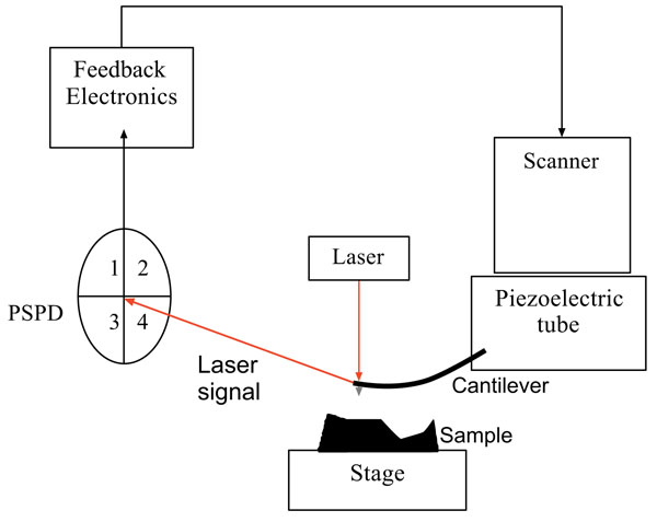
The cantilever, which is a thin, flexible beam, holds the tip to track its movement over the sample surface and deflects in the same direction in which the topography changes. AFM cantilevers generally have spring constants of about 0.1 N/m. A high flexibility stylus exerts downward forces on the sample, resulting in less distortion and damage while scanning. The cantilevers and tips are typically made from silicon, silicon nitride, or diamond. The reflected laser beam hits a Position-Sensitive Photo-Detector (PSPD) consisting of a four-segment photo-detector. The differences between the segments of photo-detector signals indicate the position of the laser spot on the detector and, consequently, the angular deflections of the cantilever. Optical lever detectors are the most common monitoring systems in AFM, and involve a focused laser beam on the end of the cantilever, directly over the tip, reflecting from a mirror to the PSPD. As seen in Fig. (1), the PSPD has four sections to monitor the movement of the tip and the laser intensity. The photo diode is sensitive to changes in the tip movement on the atomic scale. The difference between the two top segments (1 and 2) and the bottom segments (3 and 4) produces an electrical signal which signifies the vertical motion of the tip. Also, the difference between the left (1 and 3) and the right segments (2 and 4) records lateral or torsional movements of the tip [51].
The feedback loop is another main component of an AFM, which is an electrical system to hold the force constant during the movement of the tip across the sample. This control mechanism is important to create an image and the system uses the feedback loop to keep constant the force or cantilever deflection. If the tip has more, or less, interaction force across the sample, the piezoelectric tube responds by expanding or contracting to maintain the pre-set constant force between the tip and the sample.
Generally speaking, the tip interacts with the sample surface, while the piezoelectric tube adjusts its movement in all x, y and z direction. The PSPD monitors the cantilever’s movement by detecting the laser position. The resulting map in the x-y direction constructs the topography image of the surface with sub-angstrom resolution.
2.1. AFM Modes of Operation
There are several modes of operation developed for the AFM that can monitor surface properties of the sample. The primary modes of operation are static and dynamic modes that will be discussed in detail in the following sections. These different imaging modes work by measuring the interaction between the tip and the sample and lead to the topography of the surface.
2.1.1. Contact Mode
In the contact mode, also known as repulsive mode, the probe is dragged across the sample with an operation distance of less than a few angstroms. As the scanner gently traces the tip across the sample, the repulsive force causes the cantilever to bend in response to changes in topography. Because the tip is in hard contact with the surface, the stiffness of the lever needs to be less than the effective spring constant holding atoms together [49]. Most contact mode levers have a spring constant of < 1N/m.
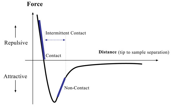
Fig. (2) shows different force regimes which correspond to inter-atomic forces. As seen in this figure, the atoms are separated by a large distance on the right side of the curve. As the atoms are brought to less than a few angstroms apart, they attract each other. This attraction increases until they come so close together that their electrons begin to keep away from each other electrostatically. This repulsive electrostatic force exceeds the attractive force as the inter-atomic separation decreases. When the distance between the atoms of the tip and those of the sample reaches a few of angstroms, which is about the length of a chemical bond, the force goes to zero. Therefore, the repulsive force balances any force that tries to push the atoms closer together, which, in terms of an AFM, means that when the cantilever pushes the tip against the sample surface, the cantilever bends instead of forcing the tip atoms closer to the sample atoms [49]. In contact mode AFM, the piezoelectric element and feedback loop control the tip deflection by holding the repulsive force constant. There are also two other methods to detect the cantilever deflection which are: constant-force mode and constant-height mode. In the constant-force mode, the speed of scanning is limited by the response time of the feedback circuitry. However, in the constant-height mode, generating topographic data is based on a fixed scanner height during scanning. In addition to the Van der Waals force explained above, there are two other forces which are important in AFM: (1) the capillary force which results from the thin layer of water present in ambient environment (around N8) and (2) the force which the cantilever exerts on the sample. The capillary force begins when water around the tip holds the tip in contact with the sample, applying a strong attractive force which depends on the tip-to-sample separation. During contact mode, this capillary force should be constant. The variable force in the contact mode is the force exerted by the cantilever, which is as analogous to the force of a compressed spring. The total force that the tip exerts on the surface is the sum of the forces exerted by the cantilever and the capillary force, which should be balanced by the repulsive force in the contact mode. The magnitude of this total force is in the range between 108 to 106N [49].
2.1.2. Non-Contact Mode
To reduce the damage to biological specimens associated with the contact mode, several vibrating techniques are utilized in AFM including non-contact or tapping modes. In non-contact AFM, the system vibrates a stiff cantilever near to its resonant frequency, which is typically from 100 to 400 kHz, with the spacing between the sample (can be seen in the Van der Waals curve, (Fig. 2) on the order of tens to hundreds of angstroms. The resonance frequency and amplitude of the oscillating probe decreases as the sample surface is approached due to interactions with Van der Waals and other long-range forces extending above the surface. These types of forces tend to be quite small (about 10-12N) relative to the repulsive forces in the contact mode. This low force is advantageous for the study of soft or elastic samples such as biological cells and does not let the surface become contaminated by contact with the tip. The stiffer cantilevers used to avoid being pulled down to the surface by the attractive forces and weak forces affecting feedback causes the non-contact AFM signal to be small, which can lead to unstable feedback and require slower scan speeds than either contact mode or tapping mode. The resonant frequency of a cantilever changes with the square root of its spring constant. The spring constant varies with the force gradient qualified by the cantilever. Furthermore, the force gradient used in the derivation of the force distance curve varies with tip-to-sample separation [49]. The feedback system in non-contact AFM keeps the resonant frequency, or vibrational amplitude, of the cantilever and tip-to-sample distance constant to generate the sample topography. In the case of imaging of rigid samples, the result from contact and non-contact mode may be the same. However, the presence of monolayers of water covering the sample surface would cause the images to look completely different. The AFM, operating in contact mode, will go through the water layers to the sample, but an AFM in non-contact mode will image the surface of the liquid layer.
2.1.3. Intermitted-Contact Mode
Intermittent-Contact, or tapping, mode is another use of dynamic AFM. In the tapping mode, the cantilever vibrates the tip close to its first bending mode resonance frequency, as in non-contact mode. However, the oscillation amplitude of the probe tip is typically much larger than used in the non-contact mode, often in the range of 20 nm to 200 nm In addition, the tip is permitted to slightly contact, or tap, the sample for a short duration during each oscillation cycle. As the tip moves toward the sample, the tip-sample interactions change the amplitude, resonance frequency, and phase angle of the oscillating cantilever. Tapping mode is a more effective means for imaging in air, particularly for soft samples, as the resolution is similar to the contact mode but with lower forces applied to the samples which mean a less destructive process. There are, however, two disadvantages of the tapping mode compared to the contact mode; (1) slightly slower scan speed and (2) more complex AFM operation. In general, tapping-mode AFM overcomes some of the limitations of both contact and non-contact AFM and becomes an important technique with improvements to lateral resolution in soft samples.
2.1.4. Peak Force Tapping Mode
In Peak Force Tapping® (PFT) mode, the probe and sample are intermittently brought together (similar to Tapping Mode) to contact the surface quickly, which eliminates lateral forces. Both normal forces and lateral forces exerted by the tip can cause damage to the sample and increase the contact area resulting in scan resolution reduction. Unlike Tapping Mode, where the feedback loop keeps the cantilever vibration amplitude constant, Peak Force Tapping® controls the maximum force (Peak Force) on the tip, and protects the tip and sample from damage by decreasing the contact area. The level of force control in PFT® can be in the range of pN, even when scanning in liquid environments. The two biggest challenges of force control in a liquid environment are nonlinear deflection variations and viscous forces when the tip and sample are not in contact. To eliminate this problem, the PFT® mode uses the feedback to maintain a constant peak force for each tap with the force range from pN to µN, depending on the application. This makes the PFT® mode significantly applicable to the imaging and measurement of plant cell walls, which are naturally sensitive to tip movement and associated damage to the structure.
2.1.4.1. Peak Force QNM
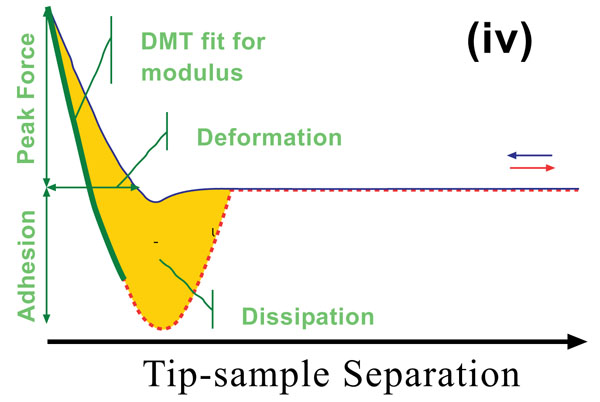
Peak Force Quantitative Nano-mechanical Mapping (Peak Force QNM) ® is a new AFM mode that uses tapping mode technology to record very fast force response curves at every pixel in the image, and uses the peak tip-sample interaction force as the feedback mechanism. Peak Force QNM® is able to simultaneously obtain quantitative modulus, adhesion, dissipation, and deformation data while imaging topography at high resolution. Also, by maintaining control of direct force to a very low level (pN), the scanning can limit indentation depths to deliver a non-destructive and high-resolution imaging technique to sensitive samples. Furthermore, material properties can be characterized over a very wide range to address samples in many different research areas. Fig. (3) shows a force curve and the parameters that can be obtained from it. The adhesion force represents the minimum force point when the tip starts to pull away from the sample. Energy dissipation is calculated by the hysteresis area between approaching and retracting processes. This dissipation includes the work associated with adhesion and viscous and plastic deformations. When the set point of the peak force is set at, or close to, zero, the energy dissipation is dominated by the work of adhesion. Deformations here represent the total penetration depth, including elastic and plastic deformations. Fig. (3) shows the force vs. separation curve instead of the force vs. distance curve. This is because of fitting purposes where the separation is calculated from the piezo position in the Z direction and the cantilever deflection.
2.1.4.2. Force Distance Curve
Force-distance curves have become a fundamental tool for the study of material properties and characterization of different known surface forces since 1989 [52]. Force-distance curves have been used in several measurements such as the determination of Hamaker constants, surface charge density, elasticity, and degrees of hydrophobicity [52]. The first study of force-distance curves acquired with an AFM focused on the surface forces on LiF and graphite [53]. When acquiring force-distance curves, the piezo element must ramp along the z-axis, which is the axis perpendicular to the surface. There are two principles modes for the acquisition of force-distance curves; static mode and non-contact mode. In the static mode, the sample is displaced along the z-axis in separate steps and the variations in cantilever deflection are collected. In the non-contact mode, the cantilever is vibrated by an additional, external piezoelectric transducer while the sample is approached and the amplitude, or the resonance frequencies, of the cantilever oscillations are collected as a function of tip-sample distance [52]. Furthermore, in 1994, other techniques were introduced using functionalized tips (tip covers) with particular molecules that adhere to one another in order to study interaction forces between specific materials by means of force-distance curves [54].
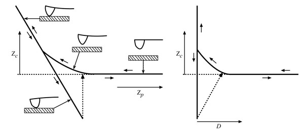
The result of a force-distance determination is a measure of the cantilever deflection, ZCs, versus the position of the piezo, Zp, normal to the surface. To acquire a force-distance curve ZC and Zpmust first be converted into force and distance. The force F can be obtained from Hook’s law as in Equation:
 |
(1) |
Where Kc is the spring constant of cantilever. The tip-sample separation, D is calculated by adding the deflection to the position, which is called ‘distance’ (Fig. 4).
 |
(2) |
The deflection of the cantilever is measured using optical lever techniques [48]. A beam from a laser diode is focused to the end of the cantilever, which is gold coated on the backside to reflect the beam towards the detector. The position of the reflected beam is monitored by a position-sensitive detector. The cantilever bends while the force is applied and the reflected light beam moves through an angle equal to twice the change in end-slope dZc/dX [54], which is given by the following equation:
 |
(3) |
For a cantilever with a rectangular cross-section defined by width, W, length, L, and the thickness, tC; with E as the Young’s modulus of the cantilever material and F is the force applied to the end of the cantilever; the deflection of the cantilever is given by:
 |
(4) |
Both approach and withdrawal force-distance curves can be generally divided into three regions; the contact line, the non-contact region, and the zero line. Zero lines are obtained when the tip is far away from the sample and the cantilever deflection is zero. The zero lines, when working in a liquid, can give information about the viscosity of the specific liquid. When the sample is pushed against the cantilever and the tip is in contact with the sample the corresponding lines in the force-distance curve are called the “Contact Lines,” which provide the information about stiffness and elastic modulus of the sample. The most interesting regions of the force-distance curve, which are related to this research, are the non-contact regions. These triangular regions contain two main parts; the jump-to-contact and jump-off-contact. The non-contact region is the approach curve which can give information about attractive or repulsive forces before contacting the sample. The maximum value of the attractive force sampled prior to contact is equal to the pull-on force, which is the product of jump-to-contact cantilever deflection and KC [52]. The non-contact region in withdrawal curves contains the jump-off-contact and the pull-off force, which is the product of jump-off-contact cantilever deflection and KC equal to the adhesion force (Fadh). Understanding of the relation between the tip and sample surface energies requires evaluating of the deformations and contact area of the sample, which are addressed by several theories.
2.2. Theories of Contact Region
The first theory regarding the contact region dates back to Hertz, who considered the tip as a smooth elastic sphere and the sample as a rigid, flat surface [55]. Based on this theory, adhesion force and surface forces are not taken into account, so the AFM experiment can follow the Hertz’s theory only in the limit of high loads or low surface forces. Hertz’s theory cannot be used to calculate sample deformations by assuming a relatively rigid tip, as in the case of the biological specimens of interest to this study.
When a rigid, spherical tip applied to an elastic surface is considered, Sneddon theory has to be engaged [52]. The force, F exerted by the tip on the surface and the surface deformation, γ are given by:
 |
(5) |
 |
(6) |
Where, K is the reduced Young’s modulus, a is the contact radius, and R is the sphere radius. Generally speaking, Hertz and Sneddon deformations, which are tip and sample deformations, can be used to calculate the total deformation when the surface forces are insignificant to an AFM measurement. There are three theories which take into account the effect of surface energy on the contact deformation, which are discussed below.
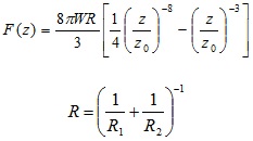
Bradley’s analysis considers two rigid spheres interacting through a Lennard-Jones potential with the total force between the spheres given by Equation 7 [52]:
 |
(7) |
Where, Z 0 is the equilibrium separation, R is the reduced radius of the spheres, and W is the adhesion work at contact.
In the Derjaguin-Muller-Toporov (DMT) theory, the external load, F, and the forces acting between the two bodies outside the contact region are considered [56]. The DMT theory is applicable for systems which have low adhesion and small tip radii.
 |
(8) |
 |
(9) |
 |
(10) |
 |
(11) |
Where, a 0 is the contact radius at zero load, γ, is the deformation of the spherical tip, and K is the reduced Young’s modulus.
The Johnson-Kendall-Roberts (JKR) theory, is suitable for highly adhesive systems with low stiffness and large tip radii, ignores long range forces outside the contact area, and considers only short range forces inside the contact region. For the JKR theory, the corresponding equations are:
 |
(12) |
 |
(13) |
 |
(14) |
 |
(15) |
In summary, Hertz’s model neglects the adhesion of the sample, while the other two theories consider adhesion outside (DMT) and inside (JKR) the contact area. Thus, Hertz’s theory can be applied only if the adhesion force is much smaller than the maximum load. In the DMT and JKR theories the work of adhesion (W) can be measured from the jump-off-contact, if the tip Radius (R) is known [54]. The JKR theory can be applied if the tip is large and the sample is soft with large adhesion and the DMT theory is applicable in the case of small tips and stiff samples with small adhesion Table 1.
| a | γ | Fadi | |
| Hertz |

|

|
0 |
| DMT |

|

|
2πRW |
| JKR |

|

|

|
Another theory, called Maugis’s theory, can describe the transition between DMT and JKR models successfully. Maugis theory is considered the most precise and complete theory applicable to all materials, from large rigid spheres with high surface energies to small compliant bodies with low surface energies. In the Maugis theory, adhesion is considered as a constant, additional stress over an annual region around the contact area. In summary, all theories which have been described are continuum elastic theories and, thus, assume smooth surfaces with no plastic deformation or viscoelastic phenomena [52].
2.3. The Zero Line
The remaining part of the force-distance curve, which shows no tip deflection, is called the zero line. The zero line corresponds to the section where the tip does not exert any force on the sample and the tip and sample are at a given distance. Though the force cannot be determined in this portion, the zero line has the great advantage that all distances are referenced to the cantilever’s rest position. Accordingly, the forces can only be measured when the deflection of the cantilever, i.e. the difference between the current deflection and the rest position, is known [52]. Furthermore, the zero lines exhibit a kind of hysteresis that results in a separation of the approach and withdrawal traces. The hysteresis of zero lines occurs due to the viscosity of the medium, where the viscous forces pull the cantilever upward when approaching the sample and cause it to twist downward as the sample is withdrawn.
2.4. Theories of Non-Contact Region
As previously mentioned, the force-distance curve includes two parts; an approach curve and a withdrawal, or retraction, curve. The approach curve, which is also called jump-to-contact, occurs when the gradient of the tip-sample force is larger than the elastic constant of the cantilever. The jump-to-contact may result from a region of attractive forces (Van der Waals or Coulomb) or repulsive forces (Van der Waals force in liquids, double-layer, hydration, and the steric) [52]. Thus, this region gives information about attraction forces between the tip and the sample. The maximum value of the attraction force is equal to the jump-to-contact cantilever deflection times the cantilever constant. This part can be predicted by any theory which includes attraction forces, such as JKR or Maugis. Pethica and Sutton [57] have demonstrated the jump-to-contact instability, which is caused by the inherent stiffness of the tip and sample materials. The instability can be predicted by employing Lennard-Jones potentials or using Molecular Dynamics (MD) simulations. It occurs when, at some small enough separation (1-2Å), the gradient of the surface forces exceed the gradient of the elastic restoring force of the bodies [52]. Also, the MD simulation by Landman et al. show the onset of instability when the tip is at a distance of 4.2Å from the sample. When the tip jumps to the surface, the distance decreases from 4.2 to 2.1Å, after which and in addition to the adhesive contact forces between the two surfaces, a partial wetting of the tip bottom by gold substrate atoms induced by adhesion is observed [52].
When the cantilever’s elastic constant is larger than the gradient of tip-sample adhesive forces the jump-off contact occurs during the withdrawal of the sample, or during retraction. The jump-off contact is related to the tip and the sample surface energies through equations that depend on the material’s dimensions, stiffness, and adhesion. The jump-off-contact deflection and the jump-off-contact distance are always greater than the jump-to-contact deflection and the jump-to-contact distance. This happens because; (1) during contact some chemical, or adhesive, bonds may cause non-conservative forces, (2) the sample deforms elastically around the tip, thereby increasing the contact area, and (3) meniscus forces exerted by layers of liquid contaminates act in opposition to the pull-off [52].
In 1995, Agrit et al. measured forces between a gold tip and a gold substrate in vacuum at liquid helium temperature shows that necks are formed during jump-to-contact and jump-off-contact and that those necks elongate during the loading or unloading process. The dependencies of pull-off force and adhesion energy on the loading force have been measured in air and in water [52].
As already discussed, in addition of using AFM as a high resolution imaging tool, results from force-distance curves can be used. This curve provides valuable mechanical property information obtained via recording of binding differences between the AFM tip and the sample. This paper focused on use of AFM to take images of intact cellulose microfibrils of plant cell walls. The test samples for AFM imaging were onion epidermis tissue. For the first time in AFM technology, PeakForce QNM, a newly developed imaging method, was used to reveal the structure of wall.
3. EXAMPLES AND INTERPRETATION
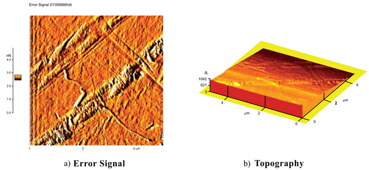
Types of AFM images include topography, error signal, amplitude and phase images. As example Fig. 5 shows the topography and the error signal for fused quartz with a silicon nitride tip and a scan size of 5µm. Error signal images are good choicees for scanning this rough sample. Error signal images can show the finer details about the fused quartz surface. There were even more difficulties in imaging this sample with a silicon nitride tip than a silicon tip. It was very tricky to make a good approach between the tip and the surface at high relative humidity (more than 60%RH).
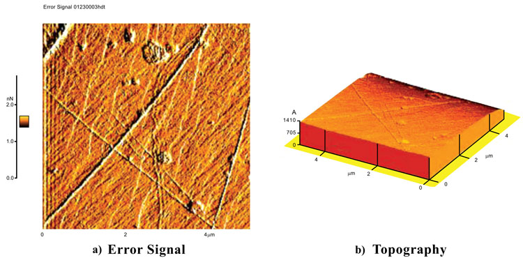
Fig. (6) shows the surface images of calcite with a scan size of 5µm with a soft silicon nitride tip. This tip has a radius of 50 nm and a force constant of 0.5 N/m. Because of the low spring constant of the tip it is excluded from U-AFM images. These current images like other results, confirm the higher reliability of error signal image than topography. The error signal image shows some scratches on the surface.
High resolution imaging of microfibrils in liquids, such as water and different chemical buffers, is very difficult with any kind of microscopy, let alone with AFM techniques. However, one important advantage of using AFM is that the sample does not require the preparations or fixations common to other techniques that can cause unrealistic changes in the properties of cellulose microfibrils. Due to the sensitivity of microfibrils to the AFM tip contact during scanning, applying a very low range of force (≈200 picoNewton) is a requirement which cannot be achieved by standard AFMs or any other microscopic techniques. To overcome this difficulty, a new mode (PeakForce Tapping mode) was added to the Dimension ICON AFM which allows for scanning a sample with extremely low forces. In a fluid environment, Peak Force Tapping is significantly more stable and reliable than the traditional tapping mode. This is because there is no need to operate at the cantilever’s resonance frequency, which is notoriously unstable in a fluid.
3.1. Celery Microfibril Characterization
The celery epidermis was bathed in 1x PBS (Phosphate Buffered Saline) solution with 0.05% detergent, called Tween 20, to remove the proteins. Due to the significant amount of Pectin, the sample needed to be bathed in solution for six hours or even longer. Due to the different structure of celery microfibrils, the preparation of a monolayer cell profile in celery epidermis was necessary and required sample preparation that was more complex and time consuming than with other samples. The celery epidermis included both multi layers and a single layer of cell, and cell profile. Therefore, finding a good position on the mono layer cells was a challenge. The sides of celery sample were glued to the clean, glass slides while the internal part remained intact and free.
The Peak Force Tapping method was used with ultra low force (picoNewton) for tapping the cantilever during scanning process. Sharp Scan Asyst Fluid + tips were used in this study with radius of curvature of 2nm. The tip was washed after each set of experiments by dipping in distilled water + 90% ethanol to remove the residue from the scanning.
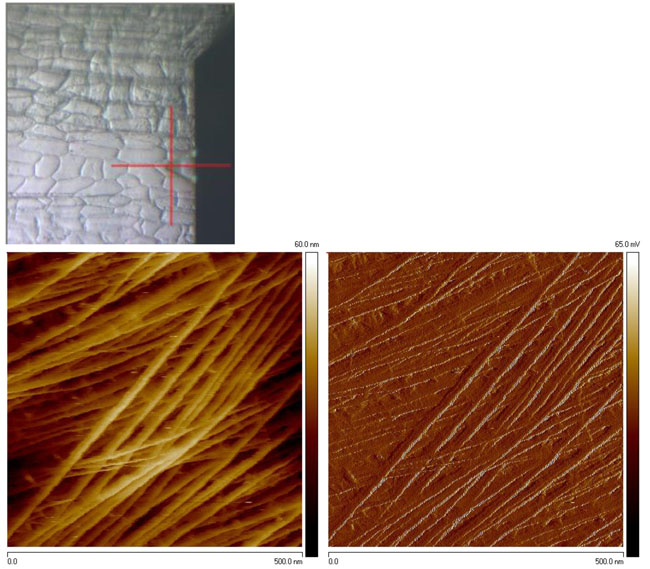
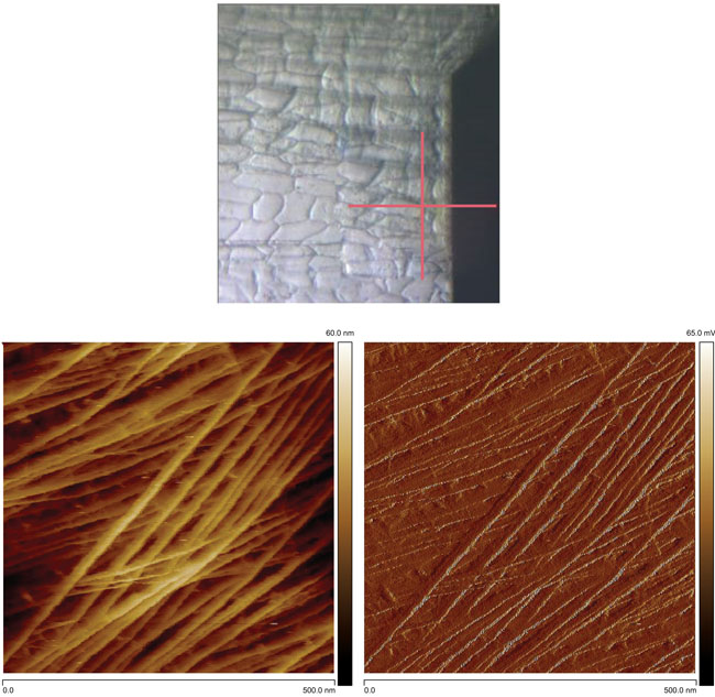
Figs. (7 and 8) show raw 500 nm and 1 µm size images of intact celery microfibrils in water. The right side images are topography, while the left side images are the Peak Force error signal images. Peak Force Error, also called error signal of deflection, is obtained by the subtraction of the set point force from detector signal (actual deflection). In general, the deflection image shows the edges of features in the topography image. In soft materials, deflection Image was clearer than the Topography Image. If the error signal was too large, which was not in our case, the tip is unable to track the sample accurately.
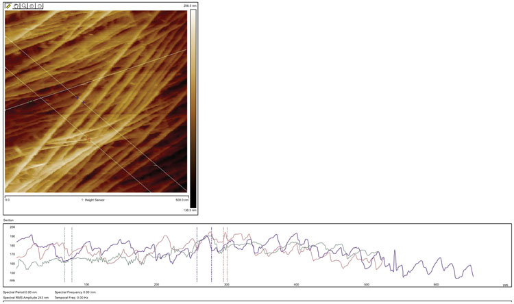
Post image processing of celery microfibrils topography or height images are shown in Fig. (9). Based on results, the red graph represents small microfibrils of 5 nm, the green was distance of 10 nm, and blue was big microfibrils bundle of 21 nm. It was determined that small differences (nanometer) in measurement could be due to the radius of curvature of the AFM tip. Generally speaking, the results for both samples show remarkable new architecture that is unique in the case of nondestructive scanning such a sensitive bio nanocompostire structure. For example, the top layer of microfibrils show an angle of 42 to 50 degrees and the second layer show an angle of 111 to 117 degrees.
4. RECENT ADVANCEMENTS IN AFM TECHNOLOGIES
Nano-scale understandings of biological samples, and the prevalence of nanotechnology generally, has changed the thinking of AFM instruments from an imaging tool to a robust nano-scale experiment platform. In addition to the applications utilizing functionalized tips and nano-elasticity measurement, progress towards the advancement of the instrument and techniques has been widespread as evident in the US and World Patent literature. In the last ten years, the US Patent Office alone has handled over 12,000 Patent applications concerning new procedures and functionality of AFM technology. Though this makes a complete review of the patent literature not realistic, selected categories of invention with examples described here-in will provide overview of the broad intellectual property landscape.
The advancement of AFM functionalities generally falls in one of three categories: 1. Improvements to instruments’ data quality, 2. New material compatibility, and 3. New measurement platforms. The first category, improvement of the instruments data quality, can be thought generally as incremental improvements which achieve goals like reducing noise in measurements and, in turn, maximizing resolution capabilities [58]. These innovations are driven dually by the scientists’ goal to investigate smaller features and the competition between manufactures to provide instruments.
Another major driver of innovation in the area of AFM technology is the need to investigate different materials that may not be compatible with traditional instruments. Specifically, the ability to test and image biological samples has created a major need for innovation in the past several years. While the traditional AFM, stemming from the Scanning Tunneling Microscope, was only initially considered for relatively hard, smooth, and dry samples; modern understanding of biological specimens have pushed the need for imaging technologies on the nano-scales, and with intact samples. This has driven inventions spanning liquid cells for maintaining living cells in the measurements environment [59], to plastic cantilever probes [60], to specific probe arrangements [61].
Finally, the most pervasive innovations to the AFM technology platform has been the extension of the device from a topographical imaging tool, to a nano-scale probe for a variety of measurements in addition to geometry. Techniques in this area of innovation span a great number of physical interactions. However, possibly the most pervasive to biological inspection is chemical force microscopy. This allows the AFM probe tip, with a selected chemical species bound to it, to approach a sample, and then measure the strength of binding between the functionalized tip and the sample surface. With the precise control the AFM offers in both force measurement and positioning, this new technique has received growing attention [62, 63].
CONCLUSION AND FUTURE WORK
This paper has tried to discuss the evolution of AFM as applied to both plant and animal cells. Recent breakthroughs in hardware and software have allowed the imaging and measurement of some mechanical properties with the cells in an aqueous medium.
Such experiments on soft biomaterials used to be very difficult to realize due to the damages that the large force from AFM tips may make on specimens. The AFM images shown are clear and with very high resolution (nanometer) in an aqueous environment.
The following can be concluded from this study:
- AFM is an effective and successful method for nondestructive evaluation of materials in nano-scale level
- Due to the sensitivity of microfibrils, a tapping technique in AFM was developed to scan the cell walls using extreme low forces (≈200 picoN)
- For the first time in AFM research, an unique architecture of intact plant cell was revealed
Future work will test competing models involving where the mechanical strength is derived from (i.e. XyG H bonded connections between micro fibrils, coated micro fibrils, or micro fibrils suspended in a matrix of polymers) can be tested by examining samples with altered compositions both through mutant plant species and synthetic cell wall analogues. Comparing cellulose microfibril movements between samples of differing cell wall composition could provide informative correlations to the role of other cell wall components (e.g., hemicelluloses, pectin, etc.) in cell wall elongation. For example, using the cell wall analogs consisting of varying degrees of cellulose, xyloglucan, and pectin could verify literature speculation as to the effects of pectin on mechanical properties by identifying the differences in the resulting structural movements of microfibrils. The relative movement of microfibrils corresponding to a given strain in composites consisting of cellulose/pectin, cellulose/hemicellulose, and cellulose/hemicellulose/pectin could be compared to the motion in pure cellulose composites. This would indicate the relative importance of each component to the emergent mechanical strength. Similarly, natural plant cell wall samples and mutants could be examined. Also this new AFM technique could be used as a possible alternative approach to the determination of how does the crystallinity vary in natural cellulose microfibers.
CONSENT FOR PUBLICATION
Not applicable.
CONFLICT OF INTEREST
The authors declare no conflict of interest, financial or otherwise.
ACKNOWLEDGEMENTS
The authors acknowledge with many thanks the help of Prof. Daniel Cosgrove, Ed Wagner, Yong Bum Park and Tian Zhang.
The authors were partially supported as part of the Center for Lignocellulose Structure and Formation (CLSF) an Energy Frontier Research Center funded by the U.S. Department of Energy, Office of Science, Office of Basic Energy Sciences under Award Number DE-SC0001090


