All published articles of this journal are available on ScienceDirect.
Hemicerebrum Infarction or Artifact: Effects of Out-of Center Positioning
Abstract
Background:
CT scans are widely used for their ability to easily and rapidly obtain medical information. However, they are also vulnerable for artifacts. Fortunately, the majority is easily recognizable or is so well known that they are included in differential diagnosis on interpreting CT and rarely cause misdiagnosis or additional investigations.
Methods:
We report 2 infants with rare CT hemicerebrum density differences. They were not consistent with the clinical condition of the patients and could be classified as being artifacts after MRI proved to be normal. Retrospectively, this could have been detected on CT by examining the eyes, which also showed not otherwise explicable density differences.
Results:
These artifacts appeared to be caused by out-of center positioning, as we could demonstrate with experimental phantom scanning. We have not found any previous reports on this type of artifact.
Conclusion:
Recognition of this specific type of artifacts by observing similar density differences in the eyes does prevent unnecessary additional imaging.
1. INTRODUCTION
CT scan (or X-ray computed tomography (X-ray CT) or computerized axial tomography scan (CAT scan)), has revolutionized neurologic imaging and diagnostic possibilities since its introduction. Although MRI can provide more detailed information, CT remains valuable due to its easy accessibility and prompt results. And especially in smaller children, there is hardly ever a necessity for sedation as opposed to MRI.
As CT makes use of complex computer-processed combinations of X-ray images taken from different angles to produce cross-sectional (tomographic) images (virtual slices), it is vulnerable for artifacts [1-3]. They can arise from a variety of factors: patient related, physics related, due to hardware or Helical and multichannel artifacts. Most artifacts are detected as they are easily recognizable, e.g. streak artifact due to differences in attenuation between high and lower density materials, or ring artifact, resulting from defect detector element). This is often encountered specially in cerebral CT. Other artifacts are so well known that they are routinely included in differential diagnosis on interpreting CT e.g. partial volume artifact occurs resulting from tissues of different absorption being encompassed in the same CT voxel producing a beam attenuation proportional to the average value of these tissues; or certain motion artifacts causing blurs, streaks or shading, similar as in plain radiographs [2,4, 5] (Table 1).
However, some rare artifacts are more difficult to recognize and may lead to erroneous interpretation, additional imaging, or sometimes treatment [6].
We report 2 infants with identical, previously unpublished CT abnormalities. These could not entirely be explained or ruled out with clinical findings, and became apparent as artifacts only after MRI was performed, which revealed no abnormalities. These artifacts appeared to be caused by off-center positioning, as we could demonstrate with experimental phantoms. Recognition of this type of artifacts does prevent unnecessary additional imaging.
2. CASE REPORT
2.1. Case A
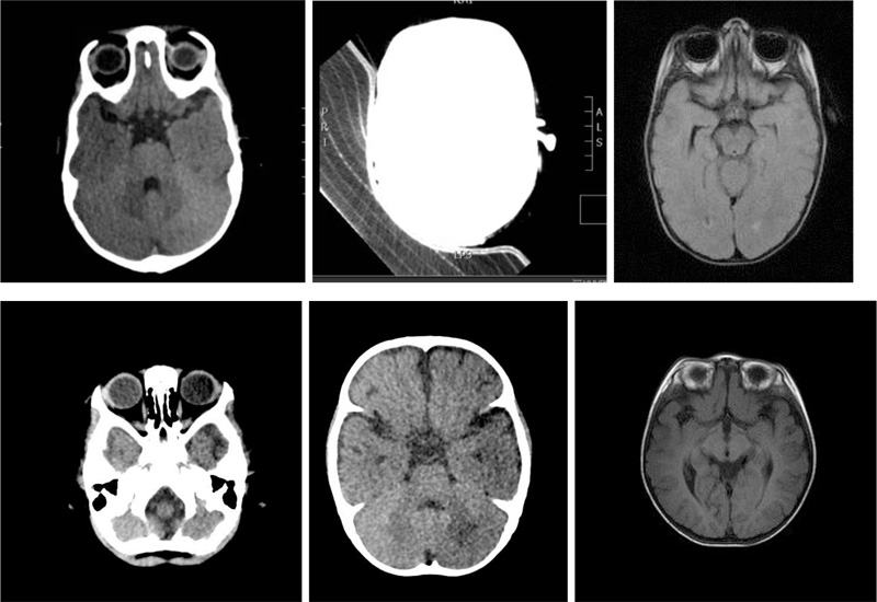
A 1-year-old girl was admitted to the emergency department with an atypical focal convulsion (tonic-clonic left arm and leg movements, drooling, decreased consciousness), for which neuroimaging was indicated. CT showed a unilateral hypodense right hemicerebrum (Fig. 1A). In combination with the clinical condition, the differential diagnosis included unilateral encephalitis, Rasmussen encephalitis, Mitochondrial Encephalomyopathy, Lactate Acidosis Stroke-like (MELAS) -syndrome, and early signs of hemispheric infarction (Dyke - Davidoff - Masson syndrome). However, additional tests and clinical course were completely normal, and thus CT artifact was presumed. Indeed the MRI showed a normal cerebrum. On re-evaluation of the CT it was noticed that the patient’s eyes showed a similar asymmetric density, paralleling the hemicerebrum densities (Fig. 1A). A reanalysis of the original scan showed the patient had been positioned out of center (Fig. 1C). This density asymmetry was absent on cerebral MRI (Fig. 1)
2.2. Case B
Patient B, a 1-year-old boy, was referred to us for a cerebral MRI, as a CT (performed because of mild neonatal macrocephaly), revealed a unilateral hypodense left hemicerebrum (Figs. 1D and E). A similar differential diagnosis was made, but given the normal clinical findings an artifact was also suspected. The MRI showed an entirely normal cerebrum (Fig. 1F). On re-evaluation of the CT it was noticed that the eyes showed similar asymmetric density, again paralleling the hemicerebrum densities, similar to patient A.
3. DISCUSSION
The images of these patients demonstrate that artifacts can remain undetected as a cause of abnormal imaging, especially as no images of scan positioning of the head is present. The asymmetric densities of the eyes, corresponding with the hemispheric differences in density, triggered us on the possibility of artifacts.
A physical explanation is that the patient has likely been positioned off-center. Due to the use of different bow-tie filters, the flux density of the radiation might be reduced and might even lead to a slightly different spectrum. According to the manufacturer, for brain scans, the patient may not be positioned outside the 320mm Field of View around the center of the scanner.
In this particular situation, the infant was positioned on a special vacuum pillow and likely positioned somewhat off-center. In addition, part of the pillow outside the ‘illuminated area’ might not be correctly accounted for in the reconstruction the so-called Field of View (FOV-artifacts which might give reconstruction errors [1].
| Patient-related artifacts | motion artifacts | - |
|---|---|---|
| - | transient interruption of contrast | - |
| - | clothing / jewelry / piercing artifacts | - |
| Physics-caused artifacts | beamhardening | cupping artifact streak and dark bands |
| - | - | metal artifact / high-density foreign material artifact |
| - | partial volume averaging | - |
| - | quantum mottle (noise) | - |
| - | photon starvation | - |
| - | aliasing / undersampling | - |
| Hardware-based artifacts | ring artifact | - |
| - | tube arcing | - |
| - | out of field artifact | - |
| - | air bubble artifact | - |
| Helical and multichannel artifacts | windmill artifact | - |
| - | cone beam effect | - |
| - | Multiplanar Reconstruction (MPR) artifact | zebra artifact |
| - | - | stair step artifact |

Fig. 1 D, E Patient B: a similar clear left-right difference in density in both the cerebral hemispheres and eyes can be observed 1F: no asymmetry in cerebral density.

3.1. Reproducing the Artifact
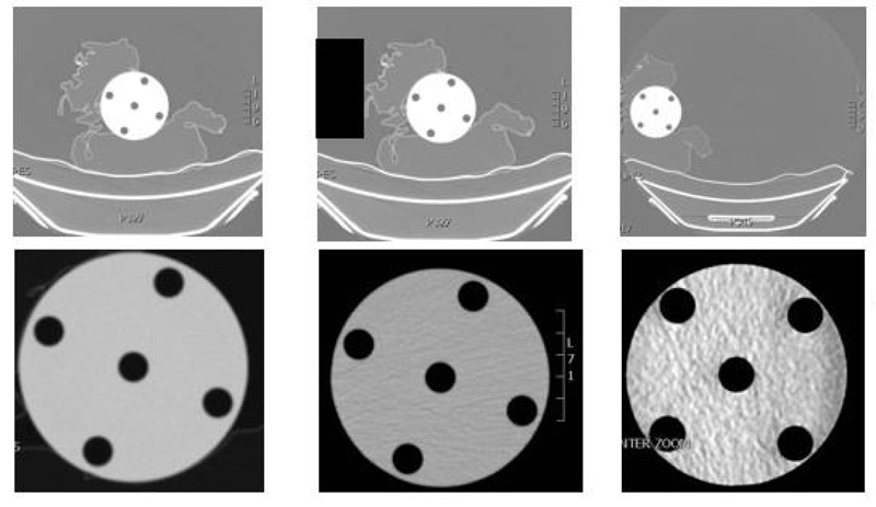
To test the hypothesis whether the artifact was caused by a high-density object next to the patient (e.g. sand pillow, as commonly used to position infants) or due to off-center positioning, phantom tests have been performed. We used the small 8 cm insert of a CTDI (Computed Tomography Dose Index) phantom, with homogenous material representative of tissue (Material: Polymethyl-Methacrylate (PMMA/Acrylic) with density: 1.19 g/cm3) and positioned the phantom with the same vacuum pillow that we use in clinical practice for small children. We positioned the phantom on different location (iso-center, off-center), with and without an absorbing sandbag on one side of the phantom. We investigated the effect of both positioning and use of an additional absorbing material on the image. Both full image (to see table position) and cropped images (as commonly stored in PACS, with automatic windowing) were used to investigate if left-right differences in the homogeneous phantom were induced due to off-centered positioning.
In (Fig. 2A-C), the CT images are shown, in the first image, the full FOV image (for the sandbag option, the full FOV image was first evaluated, however not stored and therefore, the positioning of the sand pillow is indicated in the image as black square).
In the second row, the images, reconstructed as part of FOV, as shown in PACS, are shown.
It is clear that iso-center positioning gives no artifact, thus we can conclude that the artifact is not caused by the vacuum pillow. Putting a high-density object next to the iso-center positioned phantom gives a streaking artifact but not a left-right inhomogeneity, thus excluding this absorption causing the typical artifact. However, off-center positioning leads to a lower quality scan and left-right inhomogeneity as observed in the two patients. Therefore, we assume that the combination of having both an off-center position with additionally having an extra absorbing material (as typically used in clinical practice for support upon positioning a patient) may have caused this difficult to recognize artifact.
Related artifacts: we have investigated this using literature, CT experts and the manufacturer of the CT scanner if the artifact was recognized but it is not known to be a familiar artifact and has not been reported previously. An overview of artifacts is given in all previously mentioned papers [1-5] and using reference paper by Boas and Fleischmann [2] We think the artifact that we observe is related to the pseudoenhancement artifact as discussed in their paper. However, as the artifact we observed is typically occurring in one hemisphere and not as a ring or band, it is not similar. Another artifact that leads to a one-sided shading is the incomplete projection artifact, due to absorbing tissue outside the field of view, and seems more similar to the artifact that we observed. Artifact reported with some resemblance, though much more topical is due to air bubbles in the cooling system; however, as mentioned, this only gives a circumscript local density difference [7].
CONCLUSION
CT artifacts occur often and usually are rapidly recognized and the underlying mechanism can be explained. We report a new type of artifact, showing an asymmetric density gradient between left and right hemicerebrum on CT resulting from positioning a child out of the center. Detection of asymmetric densities of the eyes corresponding with hemispheric differences can be the clue to recognition.
LIST OF ABBREVIATIONS
| CT | = Computed Tomography |
| CAT | = Computerized Axial Tomography |
| MELAS-syndrome | = Mitochondrial Encephalopathy Lactic Acidosis and Stroke-like syndrome |
| MRI | = Magnetic Resonance Imaging |
| FOV | = Field Of View |
| CDTI | = Computed Tomography Dose Index |
| PACS | = Picture Archiving and Communication System |
ETHICS APPROVAL AND CONSENT TO PARTICIPATE
Not applicable.
HUMAN AND ANIMAL RIGHTS
Not applicable.
CONSENT FOR PUBLICATION
The parents of the infants provided informed consent.
FUNDING
None.
STANDARDS OF REPORTING
CARE guidleines have been followed.
CONFLICT OF INTEREST
The authors declare no conflict of interest, financial or otherwise.
ACKNOWLEDGEMENTS
Declared none.


